RJ45 Pinout Diagrams, the Tools You Need and more!
Making RJ45 wiring easy when you have the right RJ45 pinout diagram. Several variations are shown below. I carry Ethernet cable with me all the time so you know it will be useful. To help you memorize it, I created an easy poem so you will always remember the most popular cable wiring color order. I know it’s counter-intuitive, to make something that means you won’t need to keep coming back, but to help you is my priority! I also share a video to help. Just follow the steps below to create your own. If you are looking for an Ethernet crossover cable you can make one following the steps below and paying attention to the relevant note. Read on!
The first thing you need to do when making Ethernet cable is make sure you have the right tools. While I’ll cover that further below, you can also check out TheTechMentor.com article that reviews complete network installation tool kits here.
I’ll get straight into showing the diagrams and provide more options and details further below.
Make sure you use the correct RJ45 Pinout wiring diagram for your needs.
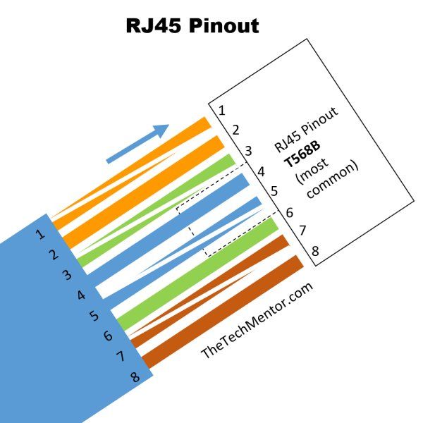
There are a couple of standards and there is also crossover cable, so make sure you study the RJ45 Pinout diagrams below to get the right one for your needs. The following is for T568 B (most common).
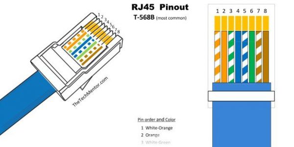
This RJ 45 pin diagram (T-568B) shows everything you need in one handy image, with iso-view and RJ45 color order, suitable for printing quite large.
I like this pinout diagram because it shows everything you need. It includes an isometric view and pin-color order table, all in one large diagram. You can print it for the wall, though the smaller one below also shows what you need within a smaller diagram which may be better to print and carry with you.
You may already know each Ethernet cable has four wire pairs.
All your Ethernet connectors (8P8C) have eight pin slots.
Always face the clip away from you so you see just the flat side with the pins. You count (or label) the cables from left to right from 1 to 8 (easy!).
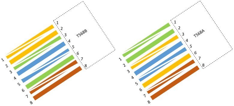
There are two standards for wiring Ethernet cables, these are T568A and T568B. T568B is the most common and is what we’ll be using for our straight Ethernet cable.
RJ45 Pinout Diagram
As I explained, the most popular and most common is the T568B standard which has surpassed the first standard (T568A). Either configurations wire the pins straight through (i.e. pins 1 through 8 on one end are connected to pins 1 through 8 on the other end, provided you wire them the same at each end).
Please do also check out the RJ45 Pinout Poem below which is easy to memorize with the aid of the diagram provided and it means you won’t ever forget it!
If you agree the poem might work for you or others, please share it with your colleagues!
Note: as stated above, the tab is away from you (hidden behind) as you count the pins 1 to 8.
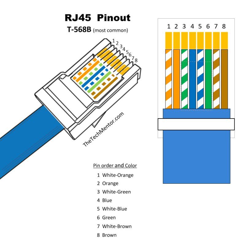
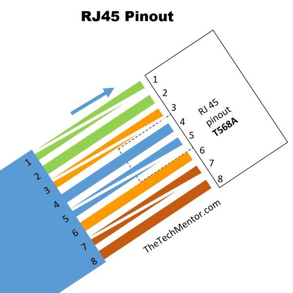
Here is a simple RJ45 Pinout Diagram (which still shows the wiring you need):
RJ45 Pinout wiring diagram (std T568B). Feel free to print it and carry it with you. If you want a larger diagram see further below. Normally a string of colors is difficult to remember similarly to phone numbers. It is surprisingly easy to memorize these colors as you’ll see. Read on to learn how!
You can follow the step by step instructions further below to make them up.
It might not be practical to always carry this RJ45 pinout diagram with you.
It can be easy to memorize the order, if you know how. I strongly recommend it. Then you can impress everyone that you have memorized it and say the colors in order quickly.
While the RJ45 B pinout wiring order is more recent and more commonly used these days, the T568 RJ45 A wiring order is still quite common (you just want to be consistent and use the crossover cable further below where necessary).
This diagram shows the original T-568 pinout wiring order. Again, as per it’s counterpart shown further above, this one is small but ideal to print and carry with you.
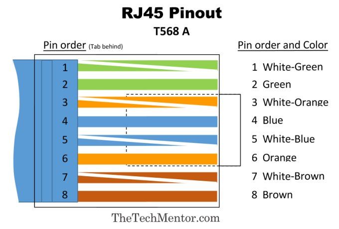
The next pinout diagram below is the counterpart for the more detailed isometric and T-568-B RJ-45 wiring above, showing rj45 pin numbers and color order for T-568 A. Can you pick which pairs are swapped relative to the T-568B wiring diagram?
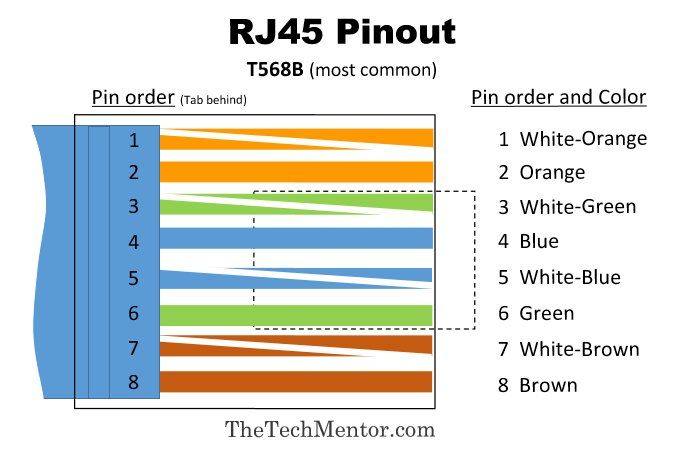
T568A Wiring Diagram with RJ45 Pin numbers and wiring order:
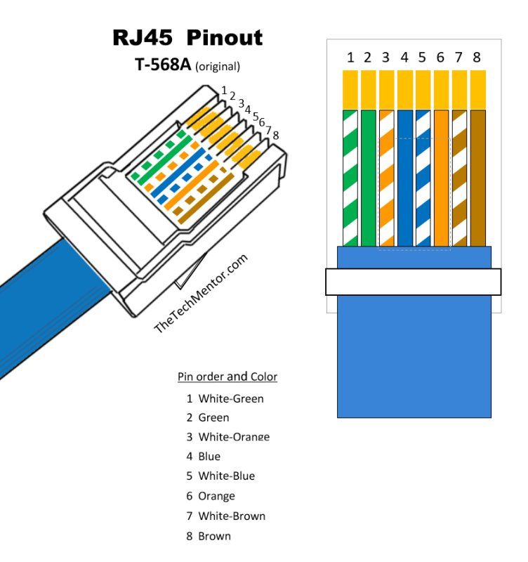
In this RJ-45 A wiring diagram you can see the isometric view and color order. The swapped wiring order pairs are explained further below.
I mentioned a way to memorize the RJ45 Pinouts. The way to do it so you never need to rely on printouts again is by using the memorization tools below.
RJ45 Pinout Poem
First a question; what thing has color that also is has the name of the color? An orange of course!
This is the first wire pair base color.
The poem below (or riddle) gives the colors of wiring to pin 1 through 8.I’ve rewritten it slightly to make more sense than the older version.
NOTE: Where you see a ‘w’ that signifies the color white which will make the combination wire when combined with the next color. You’ll see what I mean!
See further below as to how this mnemonic (memorization technique) helps you remember the RJ45 pinout order.
Remember you saw it here first on TheTechMentor.com!

The RJ-45 Pinout diagram poem and picture is for the more common T568B RJ45 wiring.
While an Orange is Orange
Whose Green eyes are Blue?
Well Blueberries in Greenland
Who want Browner Brownies too!
It works well as the construction of the poem is made to match the RJ45 pinout. The riddle, with the wire colors used, only makes sense in this order.
Memorization Techniques included:
There are several patterns, rhyming verses and emotional elements to note which really help you remember it.
- The orange is first on top and easiest of all to remember since an orange is orange! So it goes first.
- Each pair has a ‘w’ letter first combined with the following letter, thus giving the white striped wire color first of every two wires. This is a helpful pattern to remember.
- The question and answer format (2 lines each) or riddle helps keep the pattern straight.
- You’re asking what green eyes are ‘blue’ (sad). There are so many songs talking about certain color eyes being blue (sad). In this case we ask what green eyes are blue. It probably should be ‘whose’, but to make a sound closer to ‘white’ we ask ‘what’ instead.
- The answer relates to blueberries of Greenland. Remember a country that has a color – Ireland just wouldn’t work here! The sad little blueberries have to be on something – they are on the land, so they come first before the land (blue before green).
- In the end, the brownies followed by ‘too’ give a rhyme with ‘blue’. The critters want darker brown brownies like everyone else has. The last two main colors are the same (brown and brown) just as the first two main colors are the same (orange and orange).
It helps that you remember the image too, as each wire pair color is in order top to bottom (and left to right).
I recommend you draw it out, in color (optional). I suggest you do this and repeat the poem while you do it.
If you do, you will always remember the RJ45 pinout and you will not need a diagram anymore!
It’s a silly image and that also helps you remember it.
How does the poem provide the colors?
So the poem with the color codes explained is like this.
While an Orange is Orange (W-O, O)
Whose Green eyes are Blue? (W-G, B)
Well Blueberries in Greenland (W-B, G)
Who want Browner Brownies too! (W-B, B)
I’ve put a larger version below as well in case you want to take a copy.
NOTE: you are welcome to print so long as you keep TheTechMentor.com on the printed image, and if you have a website you are welcome to use on a website so long as you link back to this article. Use of the poem also requires a link back to this article (thank you).
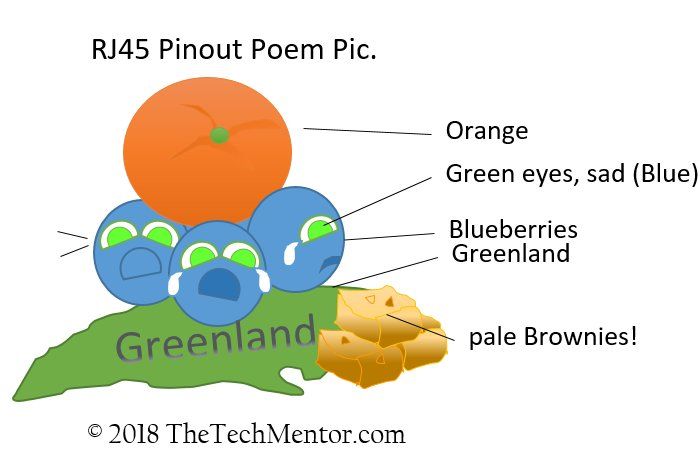
RJ45 Pinout poem picture explanation, giving WO, O, WG, B, WB, G, WB, B for the wiring to pins 1 to 8 (for T568B RJ45 wiring). [You are welcome to print so long as you keep TheTechMentor.com on the printed image, and use on a website so long as you link back to this article.]
Note: if you mumble the RJ45 Pinout Poem, it sounds like you are saying the pinout order!
Tell me what you think!
Please comment below and let me know what you think. Do you like my new Pinout Poem and think it will help you or someone you know? Is it bad? How could it be better?
Do you like my artwork (the RJ45 Pinout Poem Pic.)?
Should I not give up my day job just yet?
Okay, so you may not be interested in the poem. If not, then the tables below provide you with a serious view of the data.
Ethernet Cable Plug RJ45 Pinout (Wiring Color) Table for T568B
The table below show the proper Ethernet plug wiring with orientation of the colored wires to the pins for the Cat6 Cable we’ll make (ie. the more common T568B standard cable, with a spine). See also the diagrams further below within the step by step instructions.
| T568B Std. Ethernet Cable Plug Pin Number |
Cable Wire Color |
| 1 | White-orange |
| 2 | orange |
| 3 | White-green |
| 4 | blue |
| 5 | White-blue |
| 6 | green |
| 7 | White-Brown |
| 8 | Brown |
Ethernet RJ45 Pinout for T568A
Just for completeness I’ll list out the cable color order for the other Ethernet cable plug standard (T568A). Remember not to mix the two on one cable! Unless you want a crossover cable.
| T568A Std. Ethernet Cable Plug Pin Number |
Cable
RJ45 color |
| 1 | White-green |
| 2 | Green |
| 3 | White-Orange |
| 4 | Blue |
| 5 | White-blue |
| 6 | Orange |
| 7 | White-brown |
| 8 | Brown |
Ethernet RJ45 Crossover Cable Wiring
NOTE: Of course if you want to make a cross over cable, then you can make the cable wiring to the different standard alignments at each plug (i.e. one end will have the T568B and the other the T568A). There is also a diagram of this showing the wires in color further below.
Ethernet Crossover Cable Wiring Pinout
In RJ45 Ethernet crossover cable wiring, it is almost as easy as 1, 2, 3. They are the first three numbers to remember anyway.
Yes, here come some more memorization techniques!
You can remember which cables are switched by remembering the following:
Twelve thirty-six to thirty-six twelve, i.e.
12 36 to 36 12
(For the Ethernet cable plug pin numbering above.)
That means 1 goes to 3, 2 goes to 6; 3 goes to 1 and 6 goes to 2.
This gives you the relevant switch of T568A to T568B (and vice versa, i.e. T568 B to T568 A).
- It is easier to remember because it makes it seem like just 2 pairs of numbers, then reversed.
- First pair is 12, say like 12 months in the year.
- Second pair is 36, (well, 3 follows on from 1 and 2, and 36 is three times 12 the first pair).
- Or using 1, 2, 3: the first numbers are 1, 2 and 3, and the last number is 1 x 2 x 3 which equals 6.
It helps if you can remember that the first three numbers are 123. So easy! 3 is the hook to get the final pair, as 12 times 3 gives the second pair. There are many different memorization hooks you can use.
Still having a little difficulty visualizing the crossover pinout? Here is a diagram I hope will help.
RJ45 Crossover Cable Pinout
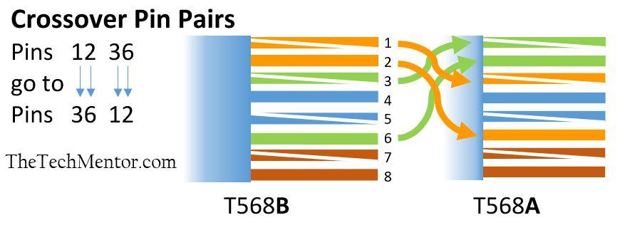
RJ45 Pinout to make an Ethernet crossover cable. This is useful to visualize the ’12’ ’36’ to ’36’ ’12’ pinout rj45 crossover pattern, making it look simpler than it sounds. Note all we really have is the orange base color pair swapping with the green base color pair.
Okay, now on with the method.
How to make an RJ45 Ethernet Patch Cable Like a Pro!
Follow the step by step instructions below.
Note: The term ‘patch’ cable is just another way to describe a shorter or room-run cable.
Step 1: Cut and Strip
The cable not you! (Wink!)
Cut and strip the cable jacket about one and a half inches to the end. As we state elsewhere we own the TRENDNet cut and strip tool, but obviously use the one of your own preference. See further below for the tool links.
Step 2: Spread the Ethernet Cable Wires
Spread the four wires apart. For Cat 5e, you can use the pull string to strip the jacket farther down if you need to, then cut the pull string. As you may know, you need to cut out the spine from a Cat 6 cables before inserting into the Ethernet cable plug.
Step 3: Untwist the Wire Pairs
Untwist the wire pairs and neatly align them in your chosen orientation based on the RJ45 pinout, my pinout poem, the table(s) above or the RJ45 Ethernet pinout image below (T568B shown).
Basic RJ45 Pinout wiring diagram T568B as you insert into the RJ45 Connector (note tab is at the back)
This is a simpler version. Otherwise you can use the more detailed RJ45 Pinout Diagram 1 above.
NOTE: Do not untwist them down the cable further than where the jacket begins; you should aim to leave as much of the cable twisted as possible.
Step 4: Cut Again (Evenly)
Cut the wires as straight as possible, about half an inch from the end of the jacket. This is important as you want them all to sit evenly inside the cable plug. If you want to, you can hold it against the boot and mark with a permanent ink pen first.
Step 5: Insert Wires Into the Ethernet Cable Plug
Carefully insert the wires all the way into the modular connector, making sure that each wire passes through the appropriate guides inside the connector. Again, make sure you reference the RJ45 pinout diagram at this crucial step until you have it memorized.
Step 6: Crimp It!
Push the connector inside the crimping tool and squeeze the crimper all the way down.
So that is one end of our RJ45 wiring.
Repeat the above steps to attach another plug to the other end of the cable.
As I wrote above, you can make an Ethernet crossover cable by making the other end as a T568A, as per the image below.
RJ45 Pinout Diagram for T568 A
The RJ45 Ethernet Pinout below is still used, it’s just that the T568B is more common these days. It effects how the wires spread out from the main cable. In the end though, so long as you make sure you use the same pinout at each end, you will have your working Ethernet cable.
Cat5 Pinout diagram showing how to make an Ethernet plug wiring as inserted into the RJ45 connector
Ideally, to make sure you’ve properly terminated each end of the cable, use a cable tester to test each pin (see the link to a cheap cable tester in the tools below). This is when you will know if you cut your wire pairs evenly enough!
RJ45 Crossover Cable Pinout
To make an Ethernet Crossover cable, your cable pugs would be terminated like so:
Ethernet crossover cable end boots. Can you see the 12 36 to 36 12 pattern? Tabs are to the back (as usual).
Now that you’ve made your cable, then what? You might like to use it as Ethernet cable for gaming in your own LAN or maybe to connect up to the internet. It is a nice feeling to stop and remind yourself that you are using the Ethernet cable you made!
Links to more info. and to buy
If you are looking for Cheap RJ45 cable plugs (Ethernet cable connectors) and Ethernet wiring etc., please see the links in this article: Network Cable tools, tips and links.
Well that wraps up this article all about RJ45 Pinout diagrams and wiring steps. I really hope you find the memorization techniques helpful so you can memorize the wiring colors. After all, that is why I created it! Please add your comments below.
Summary of how to make RJ45 Wiring Easily
I’ve shown step by step instructions how you connect each RJ45 Ethernet cable plug in order to make up your Ethernet patch cable (or RJ45 crossover cable) with a bonus video. You now have TheTechMentor.com’s RJ45 Pinout Poem, and the silly memorable image so that you might never need a pinout diagram again! Plus you now have all the RJ45 Pinout diagrams you will need to follow.

1 Comment
Tempar
November 27, 2019I second the Female to Female couplers. Keeping half a dozen or so in my glove box was a life saver back when I was doing field work.
The toner and probe kit is also seriously useful to have for a number of tasks but if the cost is off-putting you can get away using a cable tester to identify unlabelled (or incorrectly labelled) ports.
Leave A Response